印度大停电官方调查报告全文发布
http://www.gkong.com 2012-10-19 15:17
6.8亿人无电可用
一个城市7个水厂被迫关闭
超500列火车停运
交通因信号灯失灵乱成一锅粥
200多位矿工被困矿井
银行系统陷入瘫痪
超过一半以上国土面积受影响
世界纪录被连续两次刷新
......
这或许是某个电影大片里所呈现出来的灾难场景,但它真实的发生了。以上那些惊人的数据,是7月30日印度北部电网大面积停电事故所造成的,其造成的损失,如同给人们引发的思考,远不止于此...。
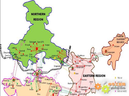
印度北部和东部大范围停电,超6亿人生活受到影响。
7月31日,印度阿姆利则,人们手捧蜡烛游行以和平的抗议方式反对旁遮普邦政府在阿姆利则不规则的电供应。
主要停电区域及受影响人口
超级大国梦碎?
7月30日凌晨,印度北方电网崩溃,3亿人口无电可用,创下世界历史上停电规模的纪录。次日,该纪录被印度自己打破,第二次大停电使6.8亿人受到影响,超过印度人口的一半。人们不禁要问了:“超级大停电”是这个“超级大国”的专利吗?
一次大停电,即便是几秒钟,其带来的破坏甚至能跟地震相比,印度大停电像是震中,世界为之震惊。金砖四国成员之一的印度像一头填不饱的能源巨兽,啃噬着本就营养不良的电力系统,在种种怪象中负重前行。7月30日停电事故发生后,被印度媒体赋予了“全球最大规模停电之国”的盛名。誉有“世界办公室”之名的印度政府,不知是不是淡定如常?
印度人自嘲称:“如果有一个比拼停电的奥运会,印度一定是金牌得主。”
《华尔街日报》8月1日文章称:“对于一个自视为新兴全球大国的国家来说,这次的停电事故令其颜面尽失。”
印度媒体也反应强烈。《印度斯坦时报》称,这肯定是国家的耻辱。8月1日,印度《经济时报》在头版赫然宣称:“超级强国印度,安息吧。”
对于一次偶然的停电事故,印度媒体为何纷纷视为印度的耻辱,它们是否过度解读?这次大停电对印度意味着什么?
在外界看来,印度一直希望成为超级大国,停电事件后,有西方媒体给印度泼冷水,英国《卫报》称,印度立志成为经济超级大国,但连续两次停电令人们严肃质疑印度的基础设施和政府满足国家能源需求的能力。美国《洛杉矶时报》文章则称,大停电凸显了印度追求超级大国的梦想和现实之间的差距。
“印度人对大停电这件事看得很重,认为它是一种耻辱。”前外交官、印度问题专家毛四维说,“西方媒体的评论是有道理的,印度追求成为超级大国的雄心和现实形成巨大的反差。”他提到,停电事件后,新德里电视台(NDTV)举行了一场辩论,题目是:无电(无能)的超级大国(Powerless Superpower):印度的超级大国梦是个笑话?
“吃一堑长一智”,或许正如印度《开放》周刊文章所指出的,“对于一个怀揣超级大国梦想的国家而言,7月30日和31日的超级大停电应被视为一记警钟。”

认可度最高的五种因素
电网缺乏统一的管理与规划
印度在经济高速发展的同时,基础设施投资、建设一直较为落后,特别缺乏对电网有效的统一管理与规划。
中国电科院杨琦博士指出,虽然印度装机容量排世界前列,但是印度电网缺乏统一的规划与建设,网架结构较为薄弱,潮流转移能力受到制约,抗事故能力较差。
杨琦说,印度是由5个区域电网构成,印度电网互联能力较差,缺乏统一的管理与规划,在较严重的事故发生后,缺乏必要的应急预案和预警措施,因此,容易造成电网事故的扩大化,导致电网的震荡、崩溃。
电力严重短缺
印度电力部部长辛德表示,经初步调查,停电事故可能与一些邦用电需求透支有关。一般而言,通过北部电网输电的正常频率范围在48.5赫兹至50.2赫兹之间,但事故发生时,监控仪器所录得的频率高出正常水平,达50.46赫兹。
辛德公开批评了北方邦、哈里亚纳邦和旁遮普邦,称它们存在用电违纪行为。他说:“很明显,这些邦使用了超出许可的用电量,以满足夏季用电高峰的需求。”
印度夏季停电事故频繁发生,用电高峰期间电力短缺现象更为凸显。数据显示,今年6至7月,印度全国断电量达3600万千瓦,相当于该国现有发电装机总容量的18%左右。另外,印度电力峰值赤字也高达12%。更值得一提的是,目前该国仍有1/4人口无法获得电力供应。印度自1951年以来,每年的电力产量都不达标,现有的发电能力为1.87亿千瓦,还不到中国发电能力的20%。印度目前主要的发电站都高度依赖污染问题严重的煤与进口原油,核能发电只占不到3%。印度希望到2050年时,核能发电比率能提高至25%。
印度总理曼莫汉星正设法为扩大电供投入4000亿美元的资金,希望在五年内能改善情况。
调控能力差
据北京大学印度问题专家韩华介绍,停电在印度不算新鲜事,她本人多次在印度遇到停电状况。短到几秒钟,多则几小时。
在电力技术和基础设施建设方面,韩华说,印度在电力基础设施建设方面太薄弱,且印度对这方面的重视和人力物力财力的投入相对匮乏。除了技术层面的问题,印度政府在电力方面的管理和调控能力很差,甚至在首都地区新德里电力的调控能力都很差,没有能够保障首都不断电的基本措施和政策。
有媒体报道称:印度电网采用四级垂直调度,分别是国调(NLDC)、区调(RLDC)、邦调(SLDC)、地调(AIDC)。在五大区域电网内,有31个省级电网以及超过100个地区电网。在日常调度中,印度调度机构对超负荷运行缺乏有效的管控。“7.30”事故中,由于北方电网一处超高压变电站出现故障,导致部分输电线路和其他变电站过负荷。
客观上说,过负荷是电网常见事故之一,通过切断负荷,可以将事故控制在较小范围。但是,由于事故引起电网发生振荡,面对跨区复杂连接的电网,统一调度往往无法在第一时间内做出正确的判断和操作,只能任由事故的连锁反应不断扩大,最终导致电网大崩溃。如果电网规模变得更为庞大,集中调度将更加难以驾驭。
政策执行不力
据《华盛顿邮报》报道,印度动力部一名官员私下透露,个别邦超配额用电,这种公开的违法行为一直在进行,中央政府拿那些强势的邦没有办法。他声称,印度中央政府受到很多政治限制,无法像发达国家那样执行电网纪律,“我们甚至不敢点那些违规的邦的名字。”
印度观察家研究基金会战略研究项目主任拉贾.莫汉表示,困扰印度电力系统的因素很多,例如,政府补助农民用电,各邦对电力超配额使用,技术落后,各邦对国家设施维护不力,以及中央与地方政府之间的紧张关系等等。
对农民用电进行政府补贴,在一些批评者看来,印度政客是用电力“行贿”农民,以取得选民的支持。农民获得电力,本来应该用来抽水灌溉他们的农田,但是印度政府官员称,很大一部分免费电力被非法用于工厂,这使得电网不堪重负,电力公司背上沉重债务。正因为如此,《印度斯坦时报》在一篇社论中称,“印度的基本能源短缺由于以政治正确的价格向消费者销售电力而加剧。”
拉贾.莫汉指出,问题的症结在于,执政党热衷于玩民粹主义那一套,指望通过口号而不是行动来赢得下一次选举,“大停电反映了印度中央政府没有推进任何部门改革的意愿,电力部门当然也不例外。”
国务院研究室综合经济司的一位官员称:上世纪80年代以前,印度各邦都有电力局,从事购电和售电业务。由于政府干预、机构臃肿、效率低下,亏损越来越严重。从1991年开始,印度引入私营发电企业。90年代中期开始进行市场化改革,发、输、配电环节皆各自分开。印度电力体制改革是在计划体制运行不下去的情况下做出的必然选择,遗憾的是,时至今日,印度电力改革没有真正做到市场化,仍然是一个计划与市场并存的体制。长期电力短缺、电网超负荷运行,是引发印度大停电的重要原因,这与他们市场化改革不到位直接相关。
电网基础设施薄弱
当地时间30日凌晨2点半左右,首都新德里、哈利亚纳、旁遮普、拉贾斯坦、北安查尔、中央邦和北方邦等9个邦的电网由于超负荷运行发生崩溃事故,整个印度北部地区基本陷入一片黑暗。在首都新德里,只有德里国际机场因为有单独的热电站供电幸免于难。负责北方电网运行的印度电力系统运营集团总裁苏尼证实了电网崩溃,并指出电网内所有火力发电厂都未能成功并网。
事实上,随着近几年印度经济的快速发展,印度原有的发电和输电体系已经远远不能满足实际的需求。尽管政府已经加大了在电力领域的投入和基础设施建设,但由于效率低下和建设周期的缘故,新投入的产能很快就被巨大的需求吞没,造成持续的电力紧缺。
前面这几大问题,虽然没有详细的阐述清此次印度停电的具体原因,但是大家关注此事的意义其实不在于事故的本身,而是背后的起因。
在印度停电原因尚未完全明确之下,大停电还是让中国紧张不已。今年4月10日,深圳的大面积停电事件给当地经济发展、社会稳定带来了较大影响,很多电力工业界人士记忆犹新。
毫无疑问,邻国印度大停电事故后,中国已拉响电网安全警报。
8月2日,国家电监会下发《关于加强电网运行管理,防范大面积停电事故的紧急通知》,要求认真排查可能发生大面积停电事故的薄弱环节和隐患。
5天后,一场轰轰烈烈的“安全日”活动在国家电网所辖各单位展开。诸多下属单位甚至全员停产一天,学习《印度大面积停电事故有关情况通报》>>点击查看,并对安全风险隐患进行再梳理、再检查。
不惟国网,南方电网科学研究院技术情报所甚至在第一时间——7月31日就撰写出了《印度北部7.30大停电事故报告》的第一版>>点击查看。报告初步分析了大停电的原因。
历次国外大停电事故之后,中国电网的检查已是常态。2003年的“美加大停电”事故后不足一月,中国国家电网公司曾以一号令的形式颁发了《关于加强调度管理确保电网安全稳定运行的规定》。
“美加‘8.14’大停电之后,中国电网对事故原因的分析甚至比美国还深入。”中国工程院院士、南方电网专家委员会秘书长李立浧说。
虽然事发距今已经2个多月了,而国内各界就印度大停电所引起的争议和评论,似乎也还没有停止。
印度官方调查报告发布
据媒体报道,事发后,印度政府方面专门成立了一个调查小组,由中央电力局、国家电网公司及电力系统运营有限公司三方代表组成的调查小组,并承诺两周后拿出事故原因的调查报告。
当时,多位专家向记者表示,“对于印度电网运行情况及数据,印方一直对我保密,印度官方调查结果一般不对外公布。”
而两周后,也就是8月16日,事故调查小组就对外发布了事故调查报告,详细论述了造成此次事故的原因。本文后半段详细刊载报告内容。注:报告内容是英文版,由于内容较长,故不予以翻译,不便之处敬请见谅!(报告内容见下页)
[page_break]
报告详细:
REPORT OF THE ENQUIRY COMMITTEE
ON
GRID DISTURBANCE
IN NORTHERN REGION
ON 30th July 2012
AND
IN NORTHERN, EASTERN & NORTH-EASTERN REGION
ON 31st JULY 2012
16th AUGUST 2012
NEW DELHI
ACKNOWLEDGEMENT
The committee gratefully acknowledges the efforts put in by all assisting members to the enquiry committee namely :
a. Shri R. N. Nayak, CMD, POWERGRID
b. Shri S. K. Soonee, CEO, POSOCO
c. Shri Balvinder Singh, IPS Retired.
The Committee places on record the efforts of Shri K. K. Agrawal, Member (GO&D), CEA for overall coordination in the whole exercise of grid disturbance enquiry.
The committee also gratefully acknowledges and places on record its appreciation towards the following members of various sub-groups, for their efforts of in-depth analysis and compilation of grid disturbance analysis:
(i) Shri Manjit Singh, Member (Thermal), CEA
(ii) Shri P.K. Pahwa, Member Secretary, NRPC,
(iii) Dr. Anil Kulkarni, IIT-B, Mumbai,
(iv) Shri Ajit Singh, Ex-Addl. Secretary, Cabinet Secretariat
(v) Shri R.K. Verma, Chief Engineer I/c (DP&D), CEA
(vi) Shri Dinesh Chandra, Chief Engineer (I/C), GM Div., CEA
(vii) Shri Ajay Talegaonkar, SE (Operation), NRPC
(viii) Shri S. Satyanarayan, SE (Operation), WRPC,
(ix) Shri D. K. Srivastava, Director, GM Div., CEA
The committee expresses its appreciation of the cooperation extended by POWERGRID and POSOCO, for making the data available from various Sub-Stations/RLDCs.
Last but not the least Committee also acknowledges the efforts of all those persons who gave their valuable support directly or indirectly.
CONTENTS Page No.
Executive Summary iv-ix
Chapter 1: Introduction 1-4
Chapter 2: Overview of the regional grids 5-7
Chapter 3: Analysis of the grid disturbance on 30th July 2012 8-20
Chapter 4: Analysis of grid disturbance on 31st July 2012 21-32
Chapter 5: Factors contributing to grid disturbances on 30th and 31st July 2012 33-39
Chapter 6: Review of islanding schemes 40-44
Chapter7: Review of restoration of generation 45-58
Chapter 8: Cyber security related aspects 59-62
Chapter 9: Recommendations of the Committee 63-70
Supplementary Volume:
A separate volume containing the relevant DR outputs during the grid disturbances on 30th and 31st July, 2012.
GLOSSARY:
ABT: Availability Based Tariff
ATC: Available Transfer Capacity
AUFLS: Automatic Under Frequency Load Shedding
BLU: Boiler Light Up
BTPS: Badarpur Thermal Power Station
CB: Circuit Breaker
CEA: Central Electricity Authority
CERC: Central Electricity Regulatory Commission
CESC: Calcutta Electric Supply Company
CTU: Central Transmission Utility
D/C: Double Circuit
DMRC: Delhi Metro Rail Corporation
DR: Disturbance Recorder
df/dt: Rate of change of frequency with time
EL: Event Logger
ER: Eastern Region
FGMO: Free Governor Mode of Operation
FSC: Fixed Series Compensation
GPS: Gas Power Station
GT: Gas Turbine
HVDC: High Voltage Direct Current
MERC: Maharashtra Electricity Regulatory Commission
NAPS: Narora Atomic Power Station
NER: North-Eastern Region
NR: Northern Region
PMU: Phasor Measurement Unit
PLCC: Power Line Carrier Communication
POSOCO: Power System Operation Corporation Ltd.
POWERGRID Powergrid Corporation of India Ltd
PPA: Power Purchase Agreement
PSS: Power System Stabilizer
RAPP: Rajasthan Atomic Power Plant
RPC: Regional Power Committee
RLDC: Regional Load Despatch Centre
SCADA: Supervisory Control and Data Acquisition System
SIL: Surge Impedance Loading
SR: Southern Region
STOA: Short Term Open Access
SVC: Static VAR Compensator
TTC: Total Transfer Capability
TCSC: Thyristor Controlled Series Compensation
UI: Unscheduled Interchange (under ABT)
VAR: Volt Ampere Reactive
WAFMS: Wide Area Frequency Measurement System
WR: Western Region
EXECUTIVE SUMMARY
There was a major grid disturbance in Northern Region at 02.33 hrs on 30-07-2012. Northern Regional Grid load was about 36,000 MW at the time of disturbance. Subsequently, there was another grid disturbance at 13.00 hrs on 31-07-2012 resulting in collapse of Northern, Eastern and North-Eastern regional grids. The total load of about 48,000 MW was affected in this black out. On both the days, few pockets survived from black out. Ministry of Power constituted an Enquiry Committee, to analyse the causes of these disturbances and to suggest measures to avoid recurrence of such disturbance in future.
The Committee analysed the output of Disturbance Recorders (DR), Event loggers (EL), PMUs, WAFMS, SCADA data and reports submitted by various SLDCs , RLDCs /NLDC, POWERGRID and generation utilities to arrive at the sequence of events leading to the blackouts on 30th July, 2012 and 31st July 2012. The Committee also interacted with POWERGRID and POSOCO on various aspects of these grid disturbances. Some teams also made field visits to sub-stations, generating stations, NRLDC, NLDC, UPSLDC and Haryana SLDC.
The Committee is of the opinion that no single factor was responsible for grid disturbances on 30th and 31st July 2012. After careful analysis of these grid disturbances, the Committee has identified several factors, which led to the collapse of the power systems on both the days, as given below:
Factors that led to the initiation of the Grid Disturbance on 30th July, 2012
a. Weak Inter-regional Corridors due to multiple outages: The system was weakened by multiple outages of transmission lines in the WR-NR interface. Effectively, 400 kV Bina-Gwalior-Agra (one circuit) was the only main AC circuit available between WR-NR interface prior to the grid disturbance.
b. High Loading on 400 kV Bina-Gwalior-Agra link: The overdrawal by some of the NR utilities, utilizing Unscheduled Interchange (UI), contributed to high loading on this tie line.
c. Inadequate response by SLDCs to the instructions of RLDCs to reduce overdrawal by the NR utilities and underdrawal/excess generation by the WR utilities.
d. Loss of 400 kV Bina-Gwalior link: Since the interregional interface was very weak, tripping of 400 kV Bina-Gwalior line on zone-3 protection of distance relay caused the NR system to separate from the WR. This happened due to load encroachment (high loading of line resulting in high line current and low bus voltage). However, there was no fault observed in the system.
Factors that led to the initiation of the Grid Disturbance on 31st July, 2012
(i) Weak Inter-regional Corridors due to multiple outages: The system was weakened by multiple outages of transmission lines in the NR-WR interface and the ER network near the ER-WR interface. On this day also, effectively 400 kV Bina-Gwalior-Agra (one circuit) was the only main circuit available between WR-NR.
(ii) High Loading on 400 kV Bina-Gwalior-Agra link: The overdrwal by NR utilities, utilizing Unscheduled Interchange (UI), contributed to high loading on this tie line. Although real power flow in this line was relatively lower than on 30th July, 2012, the reactive power flow in the line was higher, resulting in lower voltage at Bina end.
(iii) Inadequate Response by SLDCs to RLDCs’ instructions on this day also to reduce overdrawl by the NR utilities and underdrawal by the WR utilities.
(iv) Loss of 400 kV Bina-Gwalior link: Similar to the initiation of the disturbance on 30th July, 2012, tripping of 400 kV Bina-Gwalior line on zone-3 protection of distance relay, due to load encroachment, caused the NR system to separate from the WR system. On this day also the DR records do not show occurrence of any fault in the system.
Brief Sequence of Events leading to the Grid Collapse on 30th and 31st July 2012
(i) On 30th July, 2012, after NR got separated from WR due to tripping of 400 kV Bina-Gwalior line, the NR loads were met through WR-ER-NR route, which caused power swing in the system. Since the center of swing was in the NR-ER interface, the corresponding tie lines tripped, isolating the NR system from the rest of the NEW grid system. The NR grid system collapsed due to under frequency and further power swing within the region.
(ii) On 31st July, 2012, after NR got separated from the WR due to tripping of 400 kV Bina-Gwalior line, the NR loads were met through WR-ER-NR route, which caused power swing in the system. On this day the center of swing was in the ER, near ER-WR interface, and, hence, after tripping of lines in the ER itself, a small part of ER (Ranchi and Rourkela), along with WR, got isolated from the rest of the NEW grid. This caused power swing in the NR-ER interface and resulted in further separation of the NR from the ER+NER system. Subsequently, all the three grids collapsed due to multiple tripping attributed to the internal power swings, under frequency and overvoltage at different places.
(iii) The WR system, however, survived due to tripping of few generators in this region on high frequency on both the days.
(iv)The Southern Region (SR), which was getting power from ER and WR, also survived on 31st July, 2012 with part loads remained fed from the WR and the operation of few defense mechanism, such as AUFLS and HVDC power ramping.
(v) On both the days, no evidence of any cyber attack has been found by the Committee.
Measures that could have saved the system from collapse:
In an emergency system operating condition, such as on 30th and 31st July 2012, even some of the corrective measures out of the list given below might have saved the system from the collapse.
(i) Better coordinated planning of outages of state and regional networks, specifically under depleted condition of the inter-regional power transfer corridors.
(ii) Mandatory activation of primary frequency response of Governors i.e. the generator’s automatic response to adjust its output with variation in the frequency.
(iii) Under-frequency and df/dt based load shedding relief in the utilities’ networks.
(iv) Dynamic security assessment and faster state estimation of the system at load despatch centers for better visualization and planning of the corrective actions.
(v) Adequate reactive power compensation, specifically Dynamic Compensation.
(vi) Better regulation to limit overdrawal/underdrawl under UI mechanism, specifically under insecure operation of the system.
(vii) Measures to avoid mal-operation of protective relays, such as the operation of distance protection under the load encroachment on both the days.
(viii) Deployment of adequate synchrophasor based Wide Area Monitoring System and System Protection Scheme.
Restoration of the system
The Committee observed that on both the days unduly long time was taken by some of the generating units in starting the units after start up power was made available.
Recommendations of the Committee
Detailed recommendations of the committee are given in the main report, which are summarized below.
i) An extensive review and audit of the Protection Systems should be carried out to avoid their undesirable operation.
ii) Frequency Control through Generation reserves/Ancillary services should be adopted, as presently employed UI mechanism is sometimes endangering the grid security. The present UI mechanism needs a review in view of its impact on recent disturbances.
iii) Primary response from generators and operation of defense mechanisms, like Under Frequency & df/dt based load shedding and Special Protection Schemes, should be ensured in accordance with provisions of the grid code so that grid can be saved in case of contingencies.
iv) A review of Total Transfer Capability (TTC) procedure should be carried out , so that it can also be revised under any significant change in system conditions, such as forced outage. This will also allow congestion charges to be applied to relieve the real time congestion.
v) Coordinated outage planning of transmission elements need to be carried out so that depletion of transmission system due to simultaneous outages of several transmission elements could be avoided.
vi) In order to avoid frequent outages/opening of lines under over voltages and also providing voltage support under steady state and dynamic conditions, installation of adequate static and dynamic reactive power compensators should be planned.
vii) Penal provisions of the Electricity Act, 2003 need to be reviewed to ensure better compliance of instructions of Load Desptach Centres and directions of Central Commission.
viii) Available assets, providing system security support such as HVDC, TCSC, SVC controls, should be optimally utilized, so that they provide necessary support in case of contingencies.
ix) Synchrophasor based WAMS should be widely employed across the network to improve the visibility, real time monitoring, protection and control of the system.
x) Load Desptach Centres should be equipped with Dynamic Security Assessment and faster State Estimation tools.
xi) There is need to plan islanding schemes to ensure supply to essential services and faster recovery in case of grid disruptions.
xii) There is need to grant more autonomy to all the Load Despatch Centres so that they can take and implement decisions relating to operation and security of the grid
xiii) To avoid congestion in intra-State transmission system, planning and investment at State level need to be improved.
xiv) Proper telemetry and communication should be ensured to Load Despatch Centres from various transmission elements and generating stations. No new transmission element/generation should be commissioned without the requisite telemetry facilities.
xv) Start up time of generating stations need to be shortened to facilitate faster recovery in case of grid disruptions.
xvi) There is a need to review transmission planning criteria in view of the growing complexity of the system.
xvii) System study groups must be strengthened in various power sector organizations.
xviii) It was also felt that a separate task force may be formed, involving experts from academics, power utilities and system operators, to carry out a detailed analysis of the present grid conditions and anticipated scenarios which might lead to any such disturbances in future. The committee may identify medium and long term corrective measures as well as technological solutions to improve the health of the grid.
[page_break]
CHAPTER-1
INTRODUCTION
1.1 There was a major grid disturbance at 02.33 hrs on 30-07-2012 in Northern region and again at 13.00 hrs on 31-07-2012 resulting in collapse of Northern, Eastern, North-Eastern regional grids barring a few pockets.
1.2 The first disturbance which led to the collapse of Northern Regional Electricity grid occurred at 02.33 hrs on 30th July, 2012, in which all states of Northern Region viz. Uttar Pradesh, Uttarakhand, Rajasthan, Punjab, Haryana, Himachal Pradesh, Jammu & Kashmir, Delhi and Union Territory of Chandigarh were affected. Northern Regional Grid’s load was about 36,000 MW at the time of disturbance. Small islands which comprised of three units of BTPS with the load of approximately 250 MW in Delhi, NAPS on houseload, Area around Bhinmal (Rajasthan) with approximate load of 100 MW connected with Western Region survived the blackout. Restoration was completed by 16.00 hrs.
1.3 The second incident which was more severe than the previous one occurred at 13.00 hours on 31.7.2012, leading to loss of power supply in three regions of the country viz. Northern Region, Eastern Region and North Eastern Region affecting all states of Northern Region and also West Bengal, Bihar, Jharkhand, Odisha, Sikkim in Eastern region and Assam, Arunachal Pradesh, Meghalaya, Manipur, Mizoram, Nagaland and Tripura in North-Eastern region. The total load of about 48,000 MW was affected in this black out. Islands comprising of NAPS, Anta GPS, Dadri GPS and Faridabad in Northern Region, Ib TPS / Sterite, Bokaro steel and CESC survived in Eastern Region. It has been reported that major part of the system could be restored in about 5 hrs, 8hrs and 2 hrs in Northern, Eastern and North-Eastern regions respectively.
1.4 To look into the detailed causes of these disturbances and to suggest remedial measures, Ministry of Power vide its OM No. 17/1/2012-OM Dt. 30-07-2012 constituted an Enquiry Committee headed by Chairperson, CEA and CEO, POSOCO and CMD POWERGRID as members. With the second major grid disturbance on 31-07-2012 involving three regions the Ministry of Power vide its OM No. 17/1/2012-OM Dt. 03-08-2012 modified the constitution of the above enquiry committee with following members:
(i) Shri A.S. Bakshi, Chairperson, CEA Chairman
(ii) Shri A. Velayutham, Member (retd.), MERC Member
(iii) Dr. S. C. Srivastava, IIT Kanpur Member
(iv) Sh. K. K. Agrawal, Member (GO&D), CEA Member Secretary
1.5 In addition, following members assisted the Committee:
(i) Shri R. N. Nayak, CMD, POWERGRID
(ii) Shri S. K. Soonee, CEO, POSOCO
(iii) Shri Balvinder Singh, IPS Retired.
1.6 The Terms of Reference of the Committee are as under:
a) To analyse the causes and circumstances leading to the grid disturbance affecting power supply in the affected region.
b) To suggest remedial measures to avoid recurrence of such disturbance in future.
c) To review the restoration of system following the disturbances and suggest measures for improvement in this regard, if any
d) Other relevant issues concerned with safe and secure operation of the Grid.
1.7 The Committee has been asked to submit its report by 16th August, 2012. A copy of MoP OM dated 3-8-2012 constituting the above Committee is given at Annexure-1.1.
1.8 First meeting of the initially constituted Enquiry Committee was held on 01-08-2012. Second meeting of the Enquiry Committee was held on 03-08-2012 which was attended by the members of the Committee and representatives of NLDC, all RPCs, RLDCs, POSOCO and POWERGRID.
1.9 The Committee constituted five sub-groups to facilitate detailed and quick analysis of various aspects of grid disturbances viz.
(i) ‘Analysis of grid collapse on 30th& 31st July 2012 and simulation of the event’ under Shri A. Velayutham, Ex. Member, MERC and Prof. S.C. Srivastava, IIT, Kanpur assisted by Dr. Anil Kulkarni, IIT, Bombay, Shri Ajay Talegaonkar, SE (Operation), NRPC & Shri S. Satyanarayan, SE (Operation), WRPC,
(ii) ‘Islanding scheme for Railways & Delhi Metro’ under Shri K.K. Agrawal, Member (GO&D), CEA,
(iii) ‘Analysis of restoration process of thermal plants’ under Shri Manjit Singh, Member (Thermal), CEA,
(iv) ‘Islanding schemes in Northern Region’ under Shri P.K. Pahwa, Member Secretary, NRPC,
(v) ‘Cyber Security aspects’ under Shri Ajit Singh, Ex-Addl. Secretary, Cabinet Secretariat and Shri R.K. Verma, Chief Engineer I/c (DP&D), CEA
1.10 In addition, a sub-group comprising Shri Dinesh Chandra, Chief Engineer I/c and Shri D.K. Srivastava, Director, Grid Management Division was formed to compile and prepare the report based on the progress made by the five sub-groups on day-to-day basis.
1.11 For secure grid operation after two grid collapses, following steps were taken immediately:
a) NLDC reduced the TTC of the Inter-Regional lines and other critical lines limiting to its SIL thereby necessary restrictions imposed on STOA.
b) CEA advised utilities that senior and experienced officials should be available in RLDCs, SLDCs, Generating Stations and Sub-Stations for at least one week.
c) CEA also advised to all generating stations to be responsive and develop a mechanism for bringing Units at the earliest in case of contingencies.
1.12 Enquiry Committee held its third meeting on 11-8-2012. On 12-8-2012, detailed discussions were held with POSOCO and POWERGRID at NLDC, New Delhi to have their view points on the causes of grid collapse. The Committee finalized its findings in its meetings on 14th and 15th August, 2012.
1.13 The Committee analysed the output of Disturbance Recorders (DR), Event loggers (EL), PMUs, WAFMS, SCADA data and reports submitted by various SLDCs , RLDCs /NLDC, POWERGRID and generation utilities to arrive at the sequence of events leading to the blackouts on 30th July, 2012 and 31st July 2012. The Committee also interacted with POWERGRID and POSOCO on various aspects of these grid disturbances. Some teams also made field visits to sub-stations, generating stations, NRLDC, NLDC, UPSLDC and Haryana SLDC.
[page_break]
CHAPTER-2
OVERVIEW OF REGIONAL GRIDS
2.1 Power system in the country is divided into five regional grids namely Northern, Western, Southern, Eastern and North Eastern grids. Except for Southern grid, remaining four regional grid operate in synchronism. Southern grid is connected to Eastern and Western grids through asynchronous links.
2.2 Northern Regional Grid
2.2.1 Northern Region is the largest in geographical area amongst the five regions in the country covering approximately 31% of the area and having largest number of constituents. It has largest sized hydro unit (250 MW at Tehri/ Nathpa Jhakri) in the country. Northern Grid has an installed generating capacity of about 56,058 MW as on 30.06.2012 comprising 34608 MW of thermal and 19830 MW of Hydro generation The Thermal-Hydro (including renewable) mix is of the order of 64:36. The installed capacity of nuclear stations is 1620 MW.
2.2.2 Major generating stations including Super Thermal Power Stations of NTPC at Rihand and Singrauli are located in the eastern part of the NR grid. Due to such concentration of generation in the eastern part of the grid and major load centers in the central and western part of the grid there is bulk power transmission from eastern to western part over long distances. To handle this bulk transmission of power, a point to point high voltage DC line viz. HVDC Rihand-Dadri bipole with capacity of 1500 MW exists and operates in parallel with 400 kV AC transmission network besides under lying 220 kV network.
2.2.3 During the month of July, 2012 the Peak demand of Northern Region was 41,659 MW against the Demand Met of 38,111 MW indicating a shortage of 3,548 MW (8.5%). The energy requirement of Northern Region was 29,580 MU against availability of 26,250 MU indicating shortage of 3,330 MU (11.3%.).
2.3 WESTERN REGIONAL GRID
The Western Grid has an installed capacity of 66757 MW (as on 30-06-2012) consisting of 49402 MW thermal, 7448 MW hydro, 1,840 MW nuclear and 7909.95 MW from renewable energy sources.
2.4 EASTERN REGIONAL GRID
The Eastern Grid has an installed capacity of 26838 MW (as on 30-06-2012) consisting of 22545 MW thermal, 3882 MW hydro and 411 MW from renewable energy sources. The Eastern Regional grid operates in synchronism with Western, Northern and North-Eastern Regional grids.
2.5 NORTH-EASTERN REGIONAL GRID
2.5.1The North-Eastern Grid has an installed capacity of 2454.94 MW as on 31-03-2012 consisting of 1026.94 MW thermal, 1200 MW hydro and 228.00 MW from renewable energy sources. The North-Eastern Grid operated in synchronism with Northern Grid, Eastern Grid and Western Grid. North Eastern Regional Grid is connected directly only to the Eastern Regional Grid and any export of power to the other Regions has to be wheeled through the Eastern Regional Grid.
2.5.2The power transfer from North-Eastern Region to Eastern Region is taking place over Bongaigaon – Malda 400 kV D/C lines and Birpara – Salakati 220 kV D/C lines.
2.6 Inter-regional interconnections
The interconnections between various regional grids is depicted in Exhibit 2.1
[page_break]
Chapter-3
Analysis of Grid Disturbance on 30th July, 2012
3.1 Introduction
On 30th July, 2012 there was a grid disturbance in the NEW grid at 02:33:11 hrs that led to the separation of the NR grid from the rest of the NEW grid and eventually NR system collapsed. The pre-disturbance conditions, sequence of events and analysis of the disturbance are described below.
3.2 Pre-Disturbance Conditions
The details of the generation-demand and power export/import scenario in the four regions of the NEW grid on 30.07.2012 at 02:00 hrs are given below.

A number EHV lines were out prior to the disturbance and the same are listed in the enclosed Annexure- 3.1. The grid frequency, just prior to the disturbance, was 49.68 Hz.
3.3 Sequence of Events on 30th July, 2012
The committee studied the data provided by various SLDCs , RLDCs /NLDC , POWERGRID and generation utilities to analyse the sequence of events leading to the blackouts in Northern grid on 30th July, 2012. The committee experienced some difficulty in analysing the available information because of the time synchronisation problems at various stations. The committee, however, established the sequence of events based on correlation of the data from various sources like Disturbance Recorders (DRs), Event Loggers (ELs), few Phasor Measurement Units (PMUs) in the NR and WR at different stations and Wide Area Frequency Monitoring System (WAFMS) of IIT Bombay.
It may be noted that the NEW grid was operating in an insecure condition due to a large number of line outages particularly near the WR-NR interface. Though an exhaustive list of lines under outage is given at Annexure-3.1, it may be noted that the following lines had tripped within an interval of a few hours prior to the grid disturbance.
1. 220 kV Badod(WR)-Modak(NR)
2. 220 kV Badod (WR)-Kota (NR)
3. 220 kV Gwalior-Mahalgaon ckt 2 (in WR but near WR-NR interface)
4. 220 kV Gwalior(PG)-Gwalior(MP)(in WR but near WR-NR interface causing only 220 kV Gwalior-Malanpur as only 220 kV NR-WR interconnection, and 220 kV Bina-Gwalior was no longer in parallel with 400 kV Gwalior-Bina)
Following are the sequence of the events, which took place on 30th July, 2012, leading to the Northern Grid blackout:


Some of the subsequent events of cascaded tripping are listed in Annexure-3.2, which has led the NR system to practically total blackout except a few pockets, such as Badarpur and NAPS (only household loads), which survived in islanded mode.
++ Power Swings: The rotors of synchronous machines inter-connected by AC lines tend to run at the same electrical speed in steady state due to the underlying physics of this system. When this system experiences small disturbances, restorative torques bring back the machines to synchronism (i.e., the same electrical speed). This response is characterized by an oscillatory behaviour since the underlying equations which determine the transient behaviour are like those of a spring-mass system. The oscillations are called “swings” and are seen in practically all parameters including line power flows. The oscillations die down if damping is adequate.
For large disturbances (e.g faults, loss of critical transmission links), the behaviour is non-linear and the electrical torques may be unable to bring all the generators to the same electrical speed. If this happens the angular difference between the generators goes on increasing (Transient Instability or Angular Separation). This causes large variations in voltage and power flow in lines.
Other equivalent terms are “Loss of Synchronism”, “Out of Step”, “Pole slipping”, although the latter two terms are typically used if only one machine loses synchronism. In a multi-machine system groups of machines may separate.
3.4 Analysis of the Disturbance on 30th July 2012
I. It is observed that even though the frequency of the NEW grid (49.68 Hz) was near to its nominal value (50 Hz), a number of lines were not available due to either forced outages, planned outages or kept out to control high voltages. This resulted in a depleted transmission network, which, coupled with high demand in the Northern Region, resulted in an insecure state of the system operation.
II. From WR-NR interface, 400 kV Gwalior-Agra line was carrying about 1055 MW and 400 kV Zerda-Bhinmal was carrying about 369MW, while 400 kV Gwalior-Bina was carrying about 1450 MW. The loading on 400 kV Gwalior-Agra was high. The Surge Impedance Loading (SIL) of the 400 kV Gwalior-Agra and also Gwalior-Bina lines, which are 765 kV lines charged at 400 kV, is about 691 MW (uncompensated), but its thermal loading limit is much higher (for quad Bersimis conductor).
III. NR constituents were instructed by NRLDC to carry out load shedding to relieve the Gwalior-Agra line loading. However, the quantum of load shedding undertaken by the NR constituents seems to be insignificant. WRLDC also issued similar instructions to its constituents for reduction in generation.
IV. The 400 kV Agra-Gwalior line is fed from 400 kV Bina-Gwalior line in the WR.
V. At 02:33:11:907 hrs, the 400 kV Bina-Gwalior line in WR tripped on Zone 3 protection, which is due to load encroachment (DR records do not show any evidence of fault or swing). Prior to tripping the voltage was 374 kV at Bina end and the line was carrying about 1450 MW approximately as per DR report of POWERGRID for this line.
VI. With the tripping of the above line, the supply to NR from 400 kV Agra-Gwalior was lost. 400 kV Zerda-Bhinmal-Bhinmal (220 kV)-Sanchore (220 kV) and Dhaurimanna (220 kV) was the only AC tie link left between WR-NR. Subsequently 220 kV Bhinmal–Sanchore line tripped on power swing, and as per SLDC Rajasthan 220 kV Bhinmal-Dhaurimanna tripped on Zone 1distance protection. This resulted in loss of the WR-NR tie links. A small load at Bhinmal remained connected with WR system through the 400 kV Zerda-Bhinmal line.
VII. In some cases the impedance measured by a distance relay at one end of the line may reduce to a point where it is less than the tripping condition for that relay for back-up protection (Zone 3). This may happen even if there is no fault in the nearby transmission system, and may occur when the line carries a very heavy load. This phenomenon of the mal-operation of the distance relays is known as ‘Load Encroachment’. Generally, it is an unintended tripping for distance relays since no fault has actually occurred.
It may be noted that at the time of disturbance, the 400 kV Bina-Gwalior line experienced a lower voltage and higher load current (resulting in less impedance, seen by the relay, which, possibly, was below the zone-3 reach setting of the relay) caused the relay operation under load encroachment. It was informed by POSOCO that this line had not tripped earlier due to zone-3 operation under load encroachment, although few incidences of such operation of distance relays in Western Region are observed in prior disturbances.
VIII. The tripping of the 400 kV Bina-Gwalior line initiated a very large angular deviation between NR system on one side and ER+WR+NER system on the other side. The power from WR to NR was now routed via WR-ER-NR interface, which is a very long path.
IX. An illustrative simulation to understand angular separation of the WR and NR regions was carried out. The simulation confirms that the systems may separate under such conditions. The simulation details are given at Annexure-3.3
X. Due to large power flows in the WR-ER-NR route, 400 kV Jamshedpur-Rourkela double circuit (in ER) tripped on Zone 3 (Exhibit 3.1 shows the angular separation).
XI. Though the NR system, at this stage, was still connected to the ER system (which was connected to the WR), the machines in the NR system had started to slow down as compared to those in rest of the NEW grid. Therefore, angular separation between NR and the rest of the grid continued to increase. This situation would eventually lead to angular instability (loss of synchronism).
XII. It is well established that under such situations, the distance relays near the electrical center of this separation are prone to pick up. Accordingly 400 kV ties between ER and NR (BiharSharif-Balia, Muzzafarpur-Gorakhpur, Patna-Balia, and Sasaram-Balia) tripped.
XIII. Since 220 kV Pasauli-Sahupuri (ER-NR) line was operated in radial mode, Sahupuri loads remained fed from the ER system and survived.
XIV. The NR system was thereby isolated from the rest of the grid. In the NR system, there was loss of about 5800 MW import and resulted in decline of frequency. NR System has Automatic Under Frequency Load Shedding Scheme (AUFLS), which can shed about 4000 MW of loads, and df/dt relays scheme, which can shed about 6000MW of loads, to improve the frequency and save the system under such emergency situations. However, not adequate load relief from the AUFLS and df/dt relays was observed and the NR system collapsed except for a few pockets at Badarpur and NAPS.
XV. With the separation of NR from the rest of the grid, the ER+WR+NER grid had a surplus of about 5800 MW power exported to NR prior to the separation. This system had more generation and the frequency rose to 50.92 Hz and stabilized at 50.6 Hz. There was tripping of Korba (E) 2*250 MW, APL Mundra 2*660 MW, Dhuvaran 80 MW, Parli 210 MW and Nasik 210 MW units in WR and Mejia-B 400MW, DSTPS 250 MW and MPL 450MW in ER took place. APL Mundra units tripped on Special Protection Scheme. The reported loss of generation is of the order of 3340 MW.
XVI. The sudden rise in frequency, close to 51Hz in the WR, also indicates inadequate primary response from generating stations. The primary response if enabled in NR could also have helped in curtailing the initial frequency dip in the Northern region.
XVII. During restoration, at 03:39 hours, several units and transmission lines at NTPC Vindhyachal STPS tripped in Western Region which also affected the start-up process.
After the grid was restored on 30.07.2012, another grid disturbance took place on 31.07.2012 , the details of which are given in the next chapter.
List of EHV Lines Out on 30.07.2012 Prior to Disturbance
(400 kV and above and Inter-Region 220 kV and above)
(as furnished by NLDC)


Subsequent tripping of lines in ER and NR systems after separation on 30/07/2012
(only those given in the DRs are listed below)


An Illustrative Example to demonstrate angular separation of NR-WR System
In order to illustrate that the angular separation can occur with the loss of a tie, a simplified two machine system was simulated, approximately representing NR and WR systems. We can look upon this system as a simplified representation of a two area system (NR and ER-WR-NER). We consider two tie lines, one short and one long.
In the simplified system, “NR” part draws 800MW on short tie and 400 MW on the longer tie. With the tripping of the shorter tie, Fig S-1 clearly shows that both systems go out of phase (in about 2.3 sec for this simplified Illustrative example). Fig S-2 shows severe power swings and oscillatory nature of voltage, MW and MVAR flows under this condition.
This simulation illustrates that angular separation between two systems followed by power swings is possible on loss of short tie. However as it is a simplified system, for specific answers to the collapse of the grids on 30th and 31st July 2012, a detailed load flow and transient stability simulation of the NR, ER, NER and WR grids is required.


[page_break]
Chapter-4
Analysis of Grid Disturbance on 31stJuly, 2012
4.1 Introduction
While the grid recovered from the black out of 30th July 2011, another major disturbance took place on 31st July 2012 in the NEW grid at 13:00:13 hrs that led to the separation of the NR, NER and ER from the WR and eventually led to the collapse of the NR, ER and NER grids. The pre-disturbance conditions, sequence of events and analysis of the disturbance are described below.
4.2 Pre-Disturbance Conditions on 31st July 2012
The details of the generation-demand as well as import/export of power in each of the four regions in the NEW grid on 31.07.2012 at 12:30 hrs are given below.

A number of EHV lines were out prior to the disturbance and the same are listed in Annexure 4.1. It may be noted that even after grid disturbance on the previous day, similar network operating conditions prevailed on this day as well. The frequency, just prior to the disturbance, was 49.84 Hz.
4.3 Sequence of Events on 31st July, 2012
It may be noted that the NEW grid was operating in an insecure condition even on 31st July 2012 due to a large number of line outages particularly near the WR-NR and ER-WR interfaces. Though an exhaustive list of lines under outage is given at Annexure 4.1, it may be mentioned that the following lines had tripped within an interval of a few hours prior to the grid disturbance.
1. 400 kV Zerda-Bhinmal
2. 400 kV Zerda- Kankroli
3. 220 kV Badod-Modak- tripped a few minutes before the event
4. 220 kV Badod-Kota- tripped a few mintutes before the event
In addition Surat Garh unit-1 also tripped around this time
The following are the sequence of events, which took place on 31st July 2012 leading to the blackouts in the Northern, North-Eastern and Eastern regions.


**After event 64, the NR got practically isolated from the ER+NER and frequency started dropping (observed in the NR system) after a gap of about 1 minutes from the previous major event.
The subsequent events of cascaded tripping led the NR, NER and ER system to practically total blackout.
4.4 ANALYSIS OF GRID DISTURBANCE ON 31st JULY, 2012:
I. It is interesting to note that on 31st July 2012 also, though the frequency of the NEW grid (49.84 Hz) was near to its nominal value (50 Hz), a large number of lines were not available due to either forced outages, planned outages or kept out to control high voltages which, coupled with high demand in the Northern Region, resulted in insecure state of the system operation.
II. NR constituents were instructed by NRLDC to carry out load shedding to reduce the over drawal. Similarly the WR constituents were also instructed by WRLDC to reduce generation to bring down the over injection of power.
However, the quantum of load shedding/generation reduction undertaken by the two constituents seems to be insignificant.
III. Just prior to the initiation of the major disturbance, NR-WR was connected through AC tie links between 400 kV Agra-Gwalior (one circuit), 220 kV Badod-Kota and 220 kV Badod-Modak lines.
IV. Badod-Modak line flow reached 288MW at about 12:58pm on 31st July, 2012 from
V. 103MW and got tripped due to overload. Similarly, 220 kV Badod-Kota line also reached a flow of 298MW from its earlier flow of 113MW and tripped due to overload. The rise in flow of these lines are possibly due to tripping of the Suratgarh generating unit-1 of 250 MW at about 12:50 hours in Rajasthan.
VI. At about 13:00:13 hrs, 400kV Bina-Gwalior-I line tripped on distance relay zone-3 protection, which is also due to load encroachment (as DR records do not show any evidence of fault or swing). As per DR report of PGCIL the loading on this line 1254 MVA and voltage was 362 kV at Bina end (Though the MW loading was less the previous tripping, due to lower voltage the MVAR flow was larger than previous incident).
VII. The load on the 220kV Bina-Gwalior-I&II suddenly increased to 447MW from 330MW and increased further. The power flow on 220kV Gwalior(PG)-Gwalior (MP) line-II was 188MW at 12:58:58pm and got reversed to -180MW. This resulted in the reverse flow of power from Gwalior (MP) to Gwalior (PG) and pumped in to 400kV system.
VIII.The power drawl of Auraiya from Mehalgaon resulted in the tripping of 220kV Bina-Gwalior- I&II, 220kV Shivpuri-Sabalgarh-I, 132kV Pichhore-Chanderi and 132kV Pichhore-Shivpuri. On 31.07.12 400kV Bina-Gwalior II and 400kV Gwalior-Agra II lines of POWERGRID were under shut down and 220kV Gwalior (PG)-Mahalgaon (GWL) -I, 220kV Gwalior-(PG) –Malanpur-II of MP were also under shut down since 29.07.2012. This situation led to the isolation of the Gwalior region of MP from WR and formed part of the NR system.
IX. The NR system was isolated from the WR system and the demand, which was earlier fed from the WR got routed through WR-ER-NR systems,
causing increase in the angular separation between the NR and WR systems, similar to the disturbance on 30th July 2012.
X. However, unlike the pattern on 30th July 2012, the electrical center of the angular separation appears to be slightly inside the ER system from the WR-ER interface. This resulted in tripping of lines connecting unlike Ranchi and Rourkela to the rest of the ER. These buses formed part of the WR, which got separated from the rest of ER+NR+NER at about 13:00:20 hrs.
XI. The frequency plots are available from PMUs and the WAFMS from the NR and WR only (see Exhibit 4.1). This shows that the frequency in the WR rose to 51.4 Hz and that in the rest of the NEW grid stabilized close to 48.12 Hz. The sudden rise in frequency, close to 51.4 Hz in the WR, again indicates absence of FGMO controls being activated in several generating stations. In fact, the FGMO operation in the rest of the NEW grid could have possibly recovered the frequency which stayed at 48.12 Hz for about a minute and probably avoided the further catastrophic failure.
XII. The WR system survived with the tripping of Sipat 660MW, DSPM 2*250 MW ESSAR 125 MW and KLTPS 69 MW generating units. APL 660 MW generating unit tripped on Special Protection Scheme, associated with tripping of Adani-Manindragarh HVDC and frequency stabilized at around 51 Hz.
XIII.Further the loss of import from about 3000 MW import from WR resulted in decline of frequency in the rest of the NEW grid, which has Automatic Under Frequency Load Shedding Scheme (AUFLS), that can shed about 5600 MW of loads, and df/dt relays scheme, which can shed about 6020MW of loads, to improve the frequency and save the system under such emergency situations. However, not adequate load relief from the AUFLS and df/dt relays was observed on 31st July 2012 also.
XIV. Subsequently, possibly due to some generator trip in the NR+NER+ER grid led large angular oscillations and drop in system frequency, which resulted in a large number of trippings in the NR, ER and NR-ER links. This cascaded tripping of lines was on overvoltage at few places, power swing or zone-3 protection and tripping of generators on under frequency. This initially separated NR from NER+ER. From PMU records NR systems has collapsed on under frequency. There is no PMU installed so far in ER+NER system. The system is also smaller in size with small Power Number and ER+NER systems collapsed except for few islands, like CESC, NALCO and BSP.
XV. It may be mentioned that with the collapse ER, the Southern Region lost about 2000 MW in feed from Talchar-Kolar HVDC and frequency declined from 50.06 Hz to 48.88 Hz as per SRLDC SCADA. The frequency controller at HVDC Bhadrawati increased the flow of WR to SR from 880 MW to 1100 MW. System Protection scheme at Kolar did not operate. It was informed by the SRPC that there was AUFLS relief of about 984MW in the SR.
XVI. It may be noted that both on 30th and 31st July 2012, lot of tripping of lines were observed due to over voltage and also substantial under voltage at the tail end of the heavily loaded lines were observed, which caused operation of distance protection. These extreme voltage situations could have been avoided with the proper reactive power absorption/support from reactors/capacitors, dynamic compensators as well as synchronous generators.
List of EHV Lines Out on 31.07.2012 Prior to Disturbance
(400 kV and above and Inter-Region 220 kV and above)
(as furnished by NLDC)


[page_break]
Chapter- 5
FACTORS CONTRIBUTING TO GRID DISTURBANCES ON 30TH AND 31ST JULY 2012
5.1 As is the case with most system failures, no single factor was responsible for grid disturbances on 30th and 31st July 2012. After careful analysis of these grid disturbances, the Committee has identified several factors, which initiated collapse of power systems on these days. The Committee has also identified factors which could have saved the grids from total collapse. These factors are given below:
5.2 Factors that contributed to initiation of grid collapse
5.2.1 Depleted transmission network
It is observed that one circuit of 400 kV Bina-Gwalior-Agra section was taken under planned outage by POWERGRID from 11.47 AM of 28.07.2012 for up gradation to 765 kV level. A number of 400 kV lines were out prior to the incidence on both these days. The outage of 400 kV Bina-Gwalior–Agra for up-gradation work, non availability of 400 kV Zerda-Kankroli and 400 kV Bhinmal-Kankroli due to insulator problems in particular weakened the NR-WR Interface.
The availability of 400 kV Zerda-Bhinmal-Kankroli corridor requires to be improved by replacing porcelain insulators by polymer insulators at the earliest.
5.2.2 Overdrawals attributable to frequency control through commercial signals
5.2.2.1 One of the objectives of load despatch is to maintain power system parameters within permissible limits. The frequency, being one of the parameter has to be maintained at 50 Hz or close to 50 Hz. For historical reasons, the Indian grid Systems experienced poor frequency profile. In the 1990s, more loads were met with available generation at the cost of frequency. System was subjected to operate in the range of 48-51.5 Hz. Power quality and Grid security was compromised during this period. To enforce Grid discipline and to improve frequency profile, a new tariff mechanism was conceived in the early 1990s.The earlier PLF based tariff was replaced by Availability Based Tariff (ABT). Apart from fixed and variable charges, ABT had a third component, namely Unscheduled Interchange (UI) charge. UI charge is payable if an utility is deviating from schedule (Generation/drawal) depending on the frequency. ABT was first implemented in the WR on 1st,July 2002. It was possible to implement it with the regulatory support. There was positive improvement in the frequency profile. Initially the frequency band stipulated was 49.0-50.5 Hz and subsequently the range was tightened by Central Commission. The present range is 49.5-50.2 Hz. Further tightening of the frequency band by Central Commission has been challenged in the court. In the interest of power quality and grid security, there is a definite need to operate the system at and very close to 50 Hz. It is further observed that Utilities resort to load shedding to earn revenue through UI to compensate their poor financial management. If the frequency profile is close to 50 HZ, UI rate is nominal and utilities tend to over draw/under draw thereby completely deviating from the schedule. If more number of utility players resort to such activity, it may even lead to load encroachment phenomena and grid disturbance, as has been observed in recent grid disturbances. One has to draw power only through long term , medium term or short term contracts. UI mechanism, which helped the system initially, need to be reviewed now.
5.2.2.2 Electricity Act 2003 mandates that the operating frequency range defined in Grid standard(section73(d)) and Grid Code(section 79(1)(h)) has to be adopted by LDCs. Utilities rushing to court to define frequency range may not be in the interest of secured grid operation and power quality.
5.2.2.3 Just to give an example, it may be pointed out that the "Union for the Co-ordination of Transmission of Electricity" (UCTE), an association of transmission system operators in the Europe, operates at 50 Hz± 0.02 Hz . Similarly, North American Electric Reliability Council (NERC) ensures each balancing area to plan operation at 60 Hz. Though unintentional deviation take place, they are addressed without compromising the stipulated frequency. Intentional deviation is not being done as schedules are treated as binding contracts.
5.2.2. In the developed Systems, it is possible to operate at the stipulated frequency as the participating systems takes care of their load–generation balance at the stipulated frequency. In Indian Grid, Utilities have to adopt such practice for healthy system operation.
5.2.3 Inability to control flow on 400 kV Bina-Gwalior-Agra line
5.2.3.1 It is clear from the messages issued by NRLDC to various SLDCs and recorded telephonic conversations that regional load dispatcher had made desperate efforts for reduction of overdrawals by various States, which in turn would have led to relieving of loading of 400 kV Bina-Gwalior-Agra line. In spite of records of load shedding in log book of SLDCs, it is evident that there was hardly any reduction in flow on this line. It is observed that NLDC is revising TTC in case of planned outage of transmission elements and not in case of forced outage. During discussions, officials of NLDC had cited few reasons for not revising TTC on the day of disturbance. Firstly, in the opinion of NLDC, declaration of TTC is for the purpose of facilitating organized electricity trading contracts, which are cleared on day ahead basis and, therefore, revision of TTC in real time would not serve any purpose. Secondly, NLDC pointed out that calculation of TTC requires elaborate studies, which is a specialized task and cannot be performed by operators in real time. Thirdly, NLDC stated that regulatory provisions restrains them from applying congestion charges in case congestion is attributable to forced outage of transmission line in the corridor.
5.2.3.2 The very fact that provision to apply congestion charge forms part of the regulations on the issue of "Measures to relieve congestion in real time" indicates that security of the grid is main objective of such provision. However, the Committee tend to agree that calculation of TTC is a specialized task. However, ways and means can be found out to overcome this problem. The Committee has gone through relevant regulations of Central Commission. However, there is no provision which restrains NLDC from applying congestion charges. Further, para 5.4 of the "Detailed procedure for relieving congestion in real time operation" prepared by NLDC and approved by Central Commission does restrain NLDC from applying congestion charges in such situation but requires curtailment of transactions followed by revision of TTC. Thus, the procedure prepared under the provisions of a Regulation is not consistent with the Regulation. This aspect needs to be reviewed.
5.2.3.4 At present, there is no Automatic Generation Control (AGC)//tie line bias control in the network, which can automatically restrict the tie-line flows to the scheduled limit and also frequency at the nominal value.
5.2.4 Non-compliance of directions of LDCs and Regulatory Commissions
Non-compliance of instructions of RLDCs has been a problem since long. However, of late a disturbing trend of non compliance of directions of the Central Commission has been observed. The Committee is of the view that maximum penalty that can be imposed by Regulatory Commissions in accordance with the Electricity Act, 2003 is meager in comparison to damage that such non-compliance can cause to the grid. It is reported that in some cases, the penalty imposed by Central Commission has not been paid. States overdrawing from the grid often do not pay UI charges which has contributed to infectiveness of ABT.
5.2.5 Protection System Issues
5.2.5.1 It is noted that on both days, the grid disturbance was initiated by tripping of 400 kV Bina-Gwalior line on zone-3 of Main-II protection, though there were several other concurrent conditions, which ultimately led to collapse of grid. There is no doubt that this tripping is attributable to load encroachment i.e. the current and voltage conditions were such that the protection system perceived it as fault (during fault, current becomes very high and voltage goes down to very low levels). Thereafter, there were several tripping on load encroachment and power swing. It is also noted that on both days, only Main-II protections operated and Main-I protection did not pick up.
5.2.5.2 It may also be noted that during the disturbances on 30th and 31st July, 2012, the 400 kV Bina-Gwalior line was not thermally overloaded i.e., the current rating (quad Bersimis conductor) of the line was not exceeded. However, the system was “insecure”, i.e., the system was not stable for the loss of this line. System security requires that the system should be able to withstand credible contingencies.
5.3 Factors that could have saved the grid from collapse
5.3.1 Primary response from generators
5.3.1.1 The provision for putting all generating units on governor action has been part of Indian Electricity Grid Code (IEGC) for several years. However, this was not getting implemented as generators pointed out few difficulties including wide frequency fluctuations. However, in recent years, Central Commission has made concerted efforts to reduce the operating frequency band by periodically amending provisions in the IEGC and these regulatory provisions have been successful to large extent. Another difficulty cited in implementation of governor action was that the free governor action tries to lower the generation when frequency rises from a frequency lower than 50 Hz. This difficulty has also been addressed in the new IEGC issued in April 2010 by providing for restricting the governor action in such zone. In spite of the fact that impediments in implementation of governor action have been removed, there is still no evidence of governor action in Grid Disturbances on 30th and 31st July 2012. As mentioned elsewhere, had governor action been put into action during these disturbances, chances of survival of regional grid could have been more after isolation from NEW grid.
5.3.1.2 Another important aspect in relation to primary response is that it would be absolutely essential for survival of islands. In the wake of recent grid disturbances, the issue of formation of electrical islands as last resort to maintain essential services and quick restoration has come to fore. However, in case of imminent grid disturbance, if such electrical islands are formed, their chances of survival would be abysmally low if generating units included in these islands are not on governor action.
5.3.2 Optimum utilization of available assets
5.3.2.1 A large number of high capacity 400 kV lines have been added to the intra-regional and inter-regional systems in the recent past. However, a significant number of lines are generally kept open to contain high voltages. This makes system weak and such system may not be able to cope contingency. The widespread prevalence of high voltages is pointer of insufficient reactive compensation.
5.3.2.2 Practically all generating units are equipped with Power System Stabilizers (PSS), which can save the grid from several potential destabilizing conditions. However, there is need to tune PSS periodically. Similarly, various devices/equipment available in power system such as HVDC, TCSC and SVC have stability features, which need to be enabled. There is no evidence that these devices had any stabilizing influence during grid disturbances on 30th and 31st July 2012. The system requires a large of dynamic compensators, which need to be established through detailed study.
5.3.2.3 Presently, nine number of Phasor Measurement Units (PMUs) have been put in place in Northern Region and 3 PMUs have been installed in Western Region. Even these limited number of PMUs have been helpful in the past in understanding behavior of the system. Also, these PMUs have been of immense help to this Committee in analysis of grid failures on 30th and 31st July 2012. POWERGRID has plans to install PMUs in a big way, as they are bedrock requirement for development of smart transmission grids. However, it is matter of concern that on the days of disturbances, data from PMUs at Agra in Northern Region and Vindhyachal in Western Region is not available. It appears that the PMUs in Western Region are not time synchronized.
5.3.3 Operation of defense mechanism
Defense mechanisms like load shedding based on under frequency relays (UFRs) and Rate of change of frequency (df/dt) relays have been adopted in all Regional Power Committees (RPCs) in accordance with provisions of IEGC. Similarly, increasing number of Special Protection Schemes are being employed to save system in case of contingencies. However, the experience of the recent grid disturbances reveal that practically there was no load relief from these schemes. The case in point is Northern Region, where UFR based load shedding of 4000 MW (in 3 stages) and df/dt based load shedding of about 6000 MW has been agreed. The Committee is of the opinion that after loss of about 5000-6000 MW to Northern Region, had these relays operated, the grid could have been saved. The Committee has observed that so far violation of the various system security related provisions of IEGC issued by Central Commission and Grid Connectivity & Grid Standards issued by Authority has not been taken seriously and the attention has solely been on overdrawals from the grid.
5.3.4 Autonomy to Load Despatch Centres
5.3.4.1 The issue of lack of autonomy to Load Despatch Centres is on the horizon of policy makers for quite some time. In November 2007, Ministry of Power had constituted a Committee under Shri G.B. Pradhan, the then Additional Secretary in Ministry of Power. The mandate of this Committee was to examine issues relating to manpower, certification and incentives for the personnel employed on System Operation at various levels and also for ring-fencing the Load Despatch Centres to ensure their functional autonomy. This Committee had submitted its report in August 2008.
5.3.4.2 However, significant amount of efforts are required for implementation of recommendations of Pradhan Committee. One of the recommendations of the Pradhan Committee was to have qualified system operators. Towards this end, a certification programme has been started. But there is a need to provide incentives to those operators, who clear the certification examination as also recommended by the Pradhan Committee.
5.3.5 Intra-State transmission Planning and its implementation
In recent grid disturbances, it has been observed that overloading and consequent tripping of 220 kV system had pushed the system to the edge. It also appears that though inter-State system is being strengthened continuously, matching strengthening in intra-State transmission system has not been carried out. This not only limits ability of the States to draw power but also causes low voltage problems and unreliable supply to end consumers.
5.3.6 Dynamic security assessment and proper state estimation
At present the control centers do not have any tool to periodically assess the security condition of the system. They utilize only static state estimation results, which are being performed at 400 kV network at quite slow interval. The state estimator results are not quite reliable, due to non availability of data from a large number of RTUs. There is a need to arm the control centers with more advanced application functions and possibly perform the fast state estimation through synchrophasor measurements by deploying significant number of PMUs
The operators, at present, cannot readily determine whether the line loading will actually trip a relay. However, although they can, by doing an online contingency analysis, determine whether the system is secure or not. If the system is insecure (in an alert condition), the following preventive actions can be taken:
a) Use any controllable elements, like HVDC and TCSC, to re-route power flows. If continuous capability limits have been reached short time overload capabilities may be used to buy some time for other actions. The amount and effect of the rescheduling will have to be checked using online load flow/stability analysis.
b) Generation rescheduling may be attempted. An available hydro-generator may be called on to generate power.
c) Load tripping may be attempted to reduce line loading.
[page_break]
Chapter- 6
REVIEW OF ISLANDING SCHEMES
6.1 To avoid total blackout following a grid disturbance, a number of defense mechanisms and System Protection Schemes mainly comprising of generation backing down, contingency based load shedding, under frequency load shedding, df/dt load shedding etc already exist. The success of these schemes in avoiding grid disturbances to a large extent depends upon the severity, area of disturbance and system conditions prior to the disturbance. Also as a last resort some islanding schemes to save the generating stations are also in existence. During the disturbance which took place on 30th and 31st July 2012 some of the generators which survived in NR due to islanding or on house load were NAPP, BTPS , Dadri Gas, Faridabad Gas. The surviving generating units normally help in meeting essential loads and extending supply to other units within the same generating station and also to the nearby generators thereby helping in restoring the grid in reduced timeframe. The Committee reviewed the existing schemes and explored possibility of formulation of more islanding schemes in the NR.
6.2 A meeting in this regard was held on 7th August 2012 wherein members from various state utilities participated. After deliberations it was agreed that criteria for formation of islands should not be the geographical or electrical size but reliability of load-generation balance in the islands. There was agreement on the general philosophy on formation of islands, salient features of which are given below:
6.3 Guidelines for formation of islands
a) For the success of the islanding scheme, the load and generation of these islands should match and also it is necessary that generators within the island are operated with Governor action.
b) All control areas should endeavor to operationalize under frequency based load shedding scheme as first defense. Only if this defense mechanism fails and frequency continues its fall to dangerously low levels, formation of islands should be initiated as a last resort.
c) The probability of survival of islands will be realistic only when all the generating units are on free governor or on restricted governor mode in accordance with provisions of Indian Electricity Grid Code.
d) Islanding scheme could be a two-tier scheme. At frequency level of say 47.9 Hz, signal for formation of islands comprising of more than one generating stations along with pre-identified load could be initiated. However, if after the formation of island, frequency continues to fall further to say 47.7 Hz, these islands could be further broken into smaller islands comprising of single generating station with pre-identified loads.
e) For survival of the Islands, they should be created in such a manner that the possibility of generation exceeding load is more.
f) In case of hydro generators with limited pondage, islands should be created keeping peak generation in mind. This is because, in low hydro season, generation will practically be negligible during off-peak hours and hence creation of island may not serve any purpose.
g) Load-generation balance in pre-identified islands may change based on season, there would be need to review the scheme on seasonal basis. Such review should also capture network changes taking place in the interim period.
h) As far as possible, major essential loads such as hospitals etc should be incorporated in the islands. However, if this was not possible due to some reasons, efforts would be made to extend supply from these islands to essential loads on priority basis.
i) State load Dispatch Centers/ State Transmission Utilities along with the generating stations in their area should explore the possibility of formation of various islands.
6.4 Possibility of islanding of Delhi metro and Indian Railways
6.4.1 During the grid disturbances which occurred on 30th & 31st July 2012, Railways and Delhi Metro services were also affected. During the disturbance on 30th July 2012, Delhi Metro services were affected in the morning to the extent that services were delayed as the disturbance had occurred at 2:35 hours when metro services were off. This did not trouble the passengers. However, during second disturbance at 13:00 hours, the trains were in operation, and the passengers faced difficulties because of sudden stoppage of services. This problem could have been avoided if the metro network would have islanded with some generating station(s).
6.4.2 In view of the importance of Metro and other Rail network, the Committee held discussions with DMRC and Indian Railways on how islanding schemes could be developed for them.
6.5.3 Delhi Metro Rail Corporation (DMRC) have 200 trains running on 185 Kms metro rail network in Delhi fed from 13 nos. 220 kV substations, out of which one each was fed from UP and Haryana side and rest from DTL’s 220 kV network in Delhi. DMRC was using its own 33 kV network for feeding stations and 25 kV network for meeting traction load. The distance between two metro power stations was in the range of 15 to 17 Kms as higher distance resulted in voltage drop and poor traction. The peak load of Delhi Metro was 120 MW with 50 MW station load and 70 MW traction load. Load per train was about 2 MW. DMRC had installed a DG set at each metro station to meet the load of lighting, ventilation and fire-fighting during main supply failures. They needed minimum 50 MW from at least 7 infeeds for traction purpose to keep their skeletal services running only for half an hour during contingencies like islanding of Delhi system from rest of the power grid for pulling the trains to the nearest station. Though they could feed their entire network from a single point, this would result into low voltage at distant locations. It was also noted that at any point of time, 10 trains are running inside the tunnels. If the power supply fails and the train stops inside the tunnel, then battery-backup is used to keep lights & fans running inside the compartments. In the event of power failure, it is not possible to open the doors of the compartments too. Batteries could provide backup supply for about half an hour only. Thereafter, fumes from the batteries start making the environment inside the tunnel suffocating. In view of this, it is essential to move the trains out of the tunnel and bring them to the nearest station within 15 minutes of supply-failure. In case, it is not possible, then passengers needed to be evacuated from the train under the guidance of trained metro staff.
6.5.4 Indian Railways were having a supply point every 30 – 50 Km distance to feed a section. In case of requirement of reduced load by the SLDCs / RLDC due to any contingency, they could manage to keep the trains running with availability of supply at each alternate section. They have allocation of 100 MW from NTPC’s Dadri and Auraiya GPPs to meet the load of Delhi – Mughal Sarai section and their own dedicated transmission lines to draw power from the grid for the purpose. They also have supply from 2 locations in Delhi viz. Dhaula Kuan and Narela. Railways felt that this section could be considered for islanding during grid contingencies as this was one of the most important sections of Railways. They do not have allocation of power from any other central sector station to meet the load in any other section of their network in the country. For other sections, they have arrangement of supply from Distribution Companies of the concerned states and had a very good communication system between their control room and concerned SLDCs. During grid disturbances on 30th & 31st July 2012, Railways received full cooperation from SLDCs/RLDCs in restoration of supply to their network on priority, except in the Eastern Region, where supply was restored late reportedly due to non-availability of start-up power to the power stations in that region. Railways requested to get this examined and improve the arrangement of extending start-up supply in that region. Railways would abide by the advice of the power station / SLDC / RLDC in the matter of connecting load on restoration of supply after grid disturbance. They also requested their services to be given priority at the time of restoration of grid.
6.5.5 It was noted that subsequent to grid failure at 1300 hours on 31st July 2012, two gas turbines (30 MW each) were started by Delhi and charged DMRC-I & II feeders after charging other important feeders. However, within a few minutes of charging of DMRC feeders, large fluctuations in the load were observed and the GTs tripped due to fall of frequency to the level of 47.4 Hz. It was felt that this might have been caused due to sudden connection of large quantum of traction load. If the load was connected by DMRC gradually in close coordination with GT control room, the machines could have continued to operate.
6.5.6 The Committee also examined the possibility of islanding of states including Delhi in the Northern Region under a grid contingency and recommends creation of four islands in Delhi. Delhi Metro’s emergency load and a part of Indian Railways load could continue to remain connected with these islands at its minimum four different sub-stations in case of grid contingencies.
6.5.7 In case of failure of formation of islands in Delhi, Delhi Metro while availing supply from any source e.g. IP GTs, Dadri GPS, etc., should connect load in small steps in close coordination with Delhi SLDC and the generating station to avoid the possibility of tripping of the generating station. DMRC should also make necessary changes in the technical and communication arrangements in their system to ensure this. There should be reliable communication arrangement between DMRC and GT station at IP extension in Delhi. DMRC should re-distribute its load so as to make it balanced in all three phases for stable operation of connected power stations. Power could be supplied to Delhi Metro from Rithala GT station of TPDDL (one of the Distribution Companies in Delhi) as well if this station had black-start facility. There being some possibility of malfunctioning of islanding of Delhi in case of grid disturbances and delayed extension of supply thereafter, DMRC might consider installation of DG set(s) of appropriate capacity to move the trains stuck in the tunnels so as to ensure safety of passengers.
6.4.8 As regards Indian Railways, islanding scheme could be prepared for Auraiya GPS along with Railways’ and other loads. This could feed about half of Delhi-Mughal Sarai section. Remaining half could be fed from Dadri GPS, which is envisaged to be islanded with a part of Delhi’s load. In case of failure of formation of Auraiya island, Railways while availing supply from Auraiya GPS after its black-start, should connect load in small steps in close coordination with the power station to avoid the possibility of its collapse again. Keeping in view the fluctuating nature of traction load, no unit should be started with such load. However, the supply should be extended to Railways / DMRC by the power station / SLDC on priority after starting the unit(s) with other types of balanced and more or less constant loads.
6.5 As per the resolution adopted in meeting taken by Hon’ble Minister of Power with Chief Ministers and Power Ministers of Northern State on 6th August 2012 the schemes prepared by States would be deliberated by them with CEA, POWERGRID and NRPC. Indian Railway and DMRC may further firm up the islanding schemes in consultation with CEA, POWERGRID and RPCs. Other islanding schemes should also be prepared on similar lines.
相关新闻
- ▪ 2025电力与电气工程国际会议(IPEE 2025)在无锡召开
- ▪ 智能制造和电力能源融合将面临三重挑战
- ▪ 工信部等三部门联合发文推动电力装备行业稳增长 提出2025—2026年主要目标和8项举措
- ▪ “安全-低碳-创新”三维共振 “十五五”新型电力系统加速跑
- ▪ 江苏成立新型电力装备制造业创新联盟
- ▪ 我国提出的全球首个电力储能用超级电容器国际标准成功立项
- ▪ 2025年版电力自动化产业规划专项研究报告:智启电力新未来
- ▪ Eversource Energy 与 MathWorks 合作,利用概率潮流自动化将可再生能源纳入系统规划流程
- ▪ 《电力碳减排技术标准体系研究报告》发布
- ▪ 新业态激发新活力 电力系统转型加快
编辑精选
工控原创
- ▪ 珍・赫夫纳当选国际机器人联合会新任主席
- ▪ 雷赛智能上半年净利预增超55% 定增募资11.44亿加码核心部件研发
- ▪ 上半年收官!2026年6月工业自动化月度资讯汇总
- ▪ 十年深耕国产测控,简仪科技发布AI时代新战略
- ▪ 5 月 RatingDog 中国通用制造业 PMI 为 51.8 通胀压力半年来首次缓解
- ▪ NVIDIA 和宇树科技宣布推出 H2 Plus 以推进人形机器人研究
- ▪ 2026 五月智造潮工业自动化月度盘点!
- ▪ 报告:物理AI发展提速,软件已成机器人创新最大瓶颈
- ▪ 乐聚智能创业板 IPO 获受理,拟募资 26 亿元
- ▪ 施耐德电气加入世界经济论坛灯塔运营系统顾问委员会,共推开源制造蓝图